
The VUE Bullet is used for outdoor and perimeter installations where wide coverage and active deterrence is required, such as parking lots, building exteriors, and high-traffic commercial environments.
The camera can be activated on Dealer Admin, and detection regions, lines, and analytics can be configured on Dealer Admin or Virtual Keypad. To manage the camera on Virtual Keypad, refer to the following documentation:
The camera includes the following:
-
5MP resolution
-
Red and blue, and white deterrence lighting
-
Person and vehicle analytics
-
Built-in microphone and speaker
To set up the VUE Bullet camera, complete the steps below:
Step 1: Power the Camera
Option 1: Use a 12 VDC Power Supply
-
Connect a 12 VDC power supply to the camera power connector.
-
Connect a network cable to the camera Ethernet connector.
-
Connect the cable to a network switch or injector. The LEDs begin flashing when the camera is powered up.
Option 2: Use PoE
-
Connect a network cable to the camera Ethernet connector.
-
Connect the cable to a PoE switch or injector. The LEDs begin flashing when the camera is powered up
Step 2: Enable Camera Features
-
Log in to Dealer Admin (dealer.securecomwireless.com).
-
Go to Customers and select the System Name you want the camera to be associated with.
-
At the top of the screen, select Edit.
-
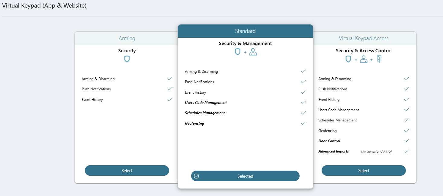
Scroll down to Virtual Keypad (App & Website) and ensure the Standard or Virtual Keypad Access plan is selected.
-
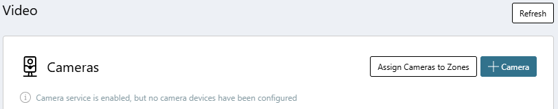
Scroll down to Video. At VUE Cameras, select the checkbox to enable camera features.

-
Select Save at the top or bottom of the screen.
Step 3: Activate the Camera on Dealer Admin
-
Log in to Dealer Admin (dealer.securecomwireless.com).
-
Go to Customers and select the System Name the camera is associated with.
-
At Video, go to Cameras and select + Camera.
-
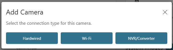
Select Hardwired.
-
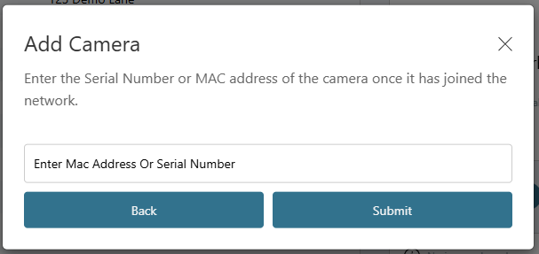
Enter the Mac Address, then select Submit.
Note: The Mac Address is printed on the box and on the back of the camera. The MAC Address can also be scanned with a barcode scanner on a mobile device.
-
Once the camera is added, it automatically checks for firmware updates. If an update is available, the camera updates to the newest firmware version. This may take several minutes.
Note: While the camera is updating, you can close the page to add additional cameras. The update continues in the background.
Step 4: Configure Camera Settings
-
Log in to Dealer Admin (dealer.securecomwireless.com).
-
Go to Customers and select the System Name the camera is associated with.
-
At Video, go to Cameras and select the VUE camera you want to configure settings for.
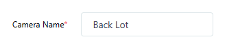
-
Enter a Camera Name.
-
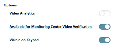
In Options, configure the following features:
-
Toggle Video Analytics ON to create regions or lines to detect people or vehicles, and to configure the onboard LEDs.
-
Available for Monitoring Center Video Verification is toggled ON by default to enable the camera’s stream for monitoring center video verification. Toggle OFF to disable this option. This only displays if this feature is enabled in System Information. Refer to Enable Monitoring Center Video Verification for more information.
-
Visible on Keypad is toggled ON by default to enable the camera view to display on an
8860 7-inch Touchscreen Keypad. This option only displays if an 8860 has been added to your system. Refer to 8860 Installation and Programming Guide for more information.
-
Note: For best user experience, when viewing video on the 8860 7-inch Touchscreen Keypad, use the Medium setting for the Video Quality.
-
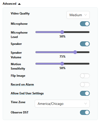
Go to Advanced to configure the following settings:
-
In Video Quality, select Low, Medium, or High to determine the video quality.
-
Microphone is toggled ON by default. Toggle OFF to disable the microphone.
-
Use the slider to adjust the microphone volume level.
-
Speaker is toggled ON by default. Toggle OFF to disable the speaker.
-
Use the slider to adjust the speaker volume level.
-
In Motion Sensitivity, use the slider to adjust how sensitive motion detection is. If Video Analytics is enabled, sensitivity is adjusted per region and does not appear under Options.
-
Toggle Flip Image ON to flip the image of the camera view.
-
Toggle Record on Alarm ON to activate recording for burglary, panic, and fire alarms.
-
Allow End User Settings is toggled ON by default to allow end users to edit camera settings in Virtual Keypad. Toggle OFF to disable this option.
-
Choose the appropriate Time Zone.
-
Observe DST is toggled ON by default. Toggle OFF if you do not want to observe Daylight Saving Time.
-
-
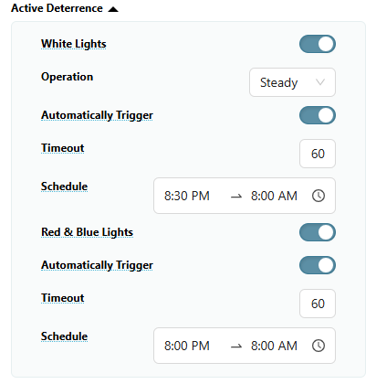
If Video Analytics is enabled, go to Active Deterrence to configure the following settings:
-
Toggle White Lights ON to use and configure the onboard white LEDs.
-
In Operation, select Steady or Flash.
-
Toggle Automatically Trigger ON to allow the LEDs to automatically turn on for a configurable amount of time when an analytic detection occurs.
-
In Timeout, enter a time between 10-60 seconds to specify how long the LEDs remain on when an analytic detection occurs. The default is 60 seconds.
-
In Schedule, select the start and end times for when the LEDs may automatically trigger. Select the

-
-
Toggle Red & Blue Lights ON to use and configure the onboard red and blue LEDs.
-
Toggle Automatically Trigger ON to allow the LEDs to automatically turn on for a configurable amount of time when an analytic detection occurs.
-
In Timeout, enter a time between 10-60 seconds to specify how long the LEDs remain on when an analytic detection occurs. The default is 60 seconds.
-
In Schedule, select the start and end times for when the LEDs may automatically trigger. Select the
-
-
-
Complete one of the following options:
-
Complete the steps below to create a region or line.
-
Select Save at the top of the screen.
-
Create a Detection Region
You can create up to 4 detection regions per camera and a total of 8 regions and lines per camera.
-
Log in to Dealer Admin (dealer.securecomwireless.com).
-
Go to Customers and select the System Name the camera is associated with.
-
At Video, go to Cameras and select the VUE camera you want to configure a region for.
-
Go to Regions and Analytics and select + Region. A blue box appears in the middle of the camera view screen.
-
Select the box, then drag it across the camera view to place it in the desired detection region. Select and drag the white circles on the corners of the box to manipulate the region.
.jpg?cb=98c9768656b3a36b04311b3727c6de94)
-
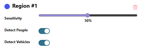
In Region #1, configure the following settings:
-
In Sensitivity, use the slider to configure the detection sensitivity.
-
Toggle People, Vehicles, or both ON if you want the camera to detect any of those options.
-
-
Complete one of the following options:
-
Repeat the steps above to create another region.
-
Complete the steps below to create a detection line.
-
Select Save at the top of the screen.
-
Create a Detection Line
Note: Ensure Video Analytics is enabled before creating a line.
You can create up to 4 detection lines per camera and a total of 8 lines and regions per camera.
-
Log in to Dealer Admin (dealer.securecomwireless.com).
-
Go to Customers and select the System Name the camera is associated with.
-
At Video, go to Cameras and select the VUE camera you want to configure a line for.
-
Go to Regions and Analytics and select + Line Cross. A blue line with orange arrows appears in the middle of the camera view screen.
-
Select the line, then drag it across the camera view to place it in the desired area. Select and drag the white circles on the ends of the line to manipulate it.
.jpg?cb=7b7a75ad1513e672318c5cb60f633916)
-
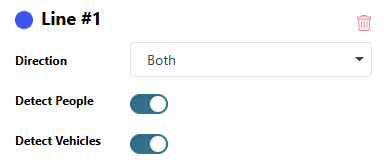
In Line #1, configure the following settings:
-
In Direction, select one of the following directions to monitor if a person or vehicle moves in a direction that crosses the detection line:
-
Enter—Motion has to cross the line in the direction of the arrow.
-
Exit—Motion has to cross the line in the direction of the arrow.
-
Both—Motion can cross the line in either direction.
-
-
Detect People and Detect Vehicles are toggled ON by default. Toggle one or both analytics OFF to disable these options.
-
-
Complete one of the following options:
-
Repeat the steps above to create another line.
-
Select Save at the top of the screen.
-
Step 5: Add Virtual Keypad App Users
Add Virtual Keypad app users so they can manage the VUE camera, which includes creating regions and lines, viewing video events, and more.
-
Log in to Dealer Admin (dealer.securecomwireless.com).
-
Go to Customers and select the customer’s name associated with the VUE camera.
-
Go to App Users, then select the Add icon.
-
Enter the user’s Email, First Name, and Last Name.
-
Select one of the following authority levels:
-
Administrator—The user can manage multiple systems.
-
Standard—The user can manage a single system.
-
Access Only—The user has temporary door access.
-
-
If you want to email the user video clips, select the checkbox next to Email Video Clips.
-
Select the systems you want the user to have authority to access.
-
Choose if you want users to be able to View User Codes or Enable Reports. If you want to allow Virtual Keypad users to initiate a system panic from the app and website, enable any of the following options:
-
Police Panic
-
Fire Panic
-
Emergency Panic
-
-
Select Save. After you add an app user on Dealer Admin, the user is sent a welcome email with a link to finish setting up their Virtual Keypad account by creating a password.
-
Configure additional settings as needed or refer users to the following documentation:
Step 6: Mount the Camera
Adjust the Camera View (Optional)
-
Adjust the pan, tilt, and camera rotation angle as needed.
-
Complete the steps below to mount the camera to the desired location.
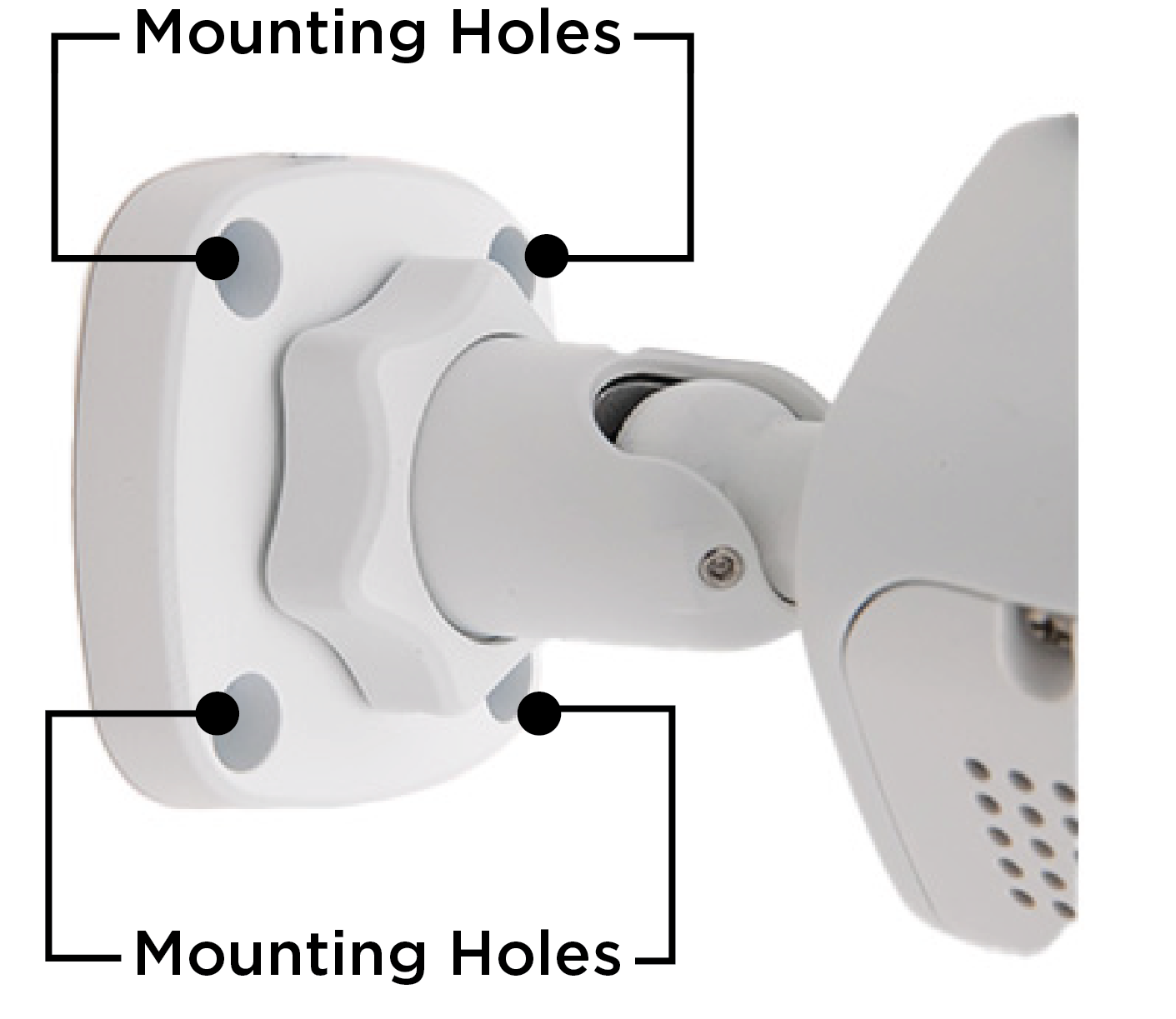
Mount the Camera
Note: Before mounting, ensure the mounting surface can hold five times the camera’s weight.
-
Place the mounting template at the location you want to mount the camera.
-
Drill holes into the mounting template.
-
Use the included screws and wall anchors to mount the camera to the wall or ceiling.
-
Remove any film covering the lens or other components.